
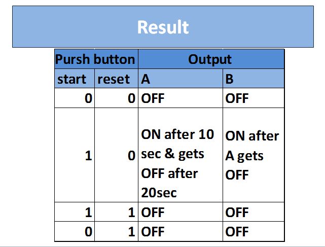
Q. 10 sec after output A comes ON, output B comes ON and remain ON even if output A goes off after next 20 sec's. This can be reset only by RESET instruction.


Solution :-
Here I:1/0 is start button and I:1/1 is the reset button 

  • Here a start NO contact is used with address I:1/0 and reset NC contact is connected in series with the NO start contact. when the star button is pressed output coil with address B3:0/0 gets activated which is nothing but a internal really which further set the parallel connected NO contact B3:0/0 ON.
  • In second rung of program, activated B3:0/0 set the timer T4:0 ON.
  • We have given the preset value of timer T4:0 as a 30 sec which is nothing but a total time duration for which output A and B ON. 
  • In third run of the program B3:0/0 is connected in series with grater than comperator and timers Done bit NC contact and then connceted to the Output A.You will get the same results if eliminate the first B3:0/0 NO contact in third rung.
  • In third rung when the timers accumulator value is more than 10 sec and less than 30 sec Output A gets activated.
  • When the accumulator value is more than 30 sec done  bit gets activated and in fourth rung Output B gets activated and remain ON till we press the reset value.

Comments

Popular posts from this blog

Timers in Siemens PLC Simatic manager

Timer :- Timer is nothing but a specialized clock in a programming software used to count the preset time intervals. In   Siemens PLC we have various ty pes of timers as :- 1) S_PULSE(Pulse timer), 2) S_PEXT(Extended Pulse Timer), 3) S_ODT(On Delay Timer), 4) S_ODTS(Retentive On Delay Timer), 5) S_OFFDT(Off Delay Timer). You must find out another five instruction sets in Timer Block in Simatic Manager STEP 7 as :- -(SP) pulse timer coil, -(SE) extended pulse timer coil, -(SD) on delay timer coil, -(SS) retentive on delay timer coil, -(SF) off delay timer coil. 1) S_PULSE(Pulse timer) :- S_PULSE Timer   Above Fig Shows how to use this timer in programming software,in this fig i have used 5 sec as a preset value, If you want to change it replace the 5 with any duration you want in S5T# 5 S.    In S_PULSE timer if input to timer is ON then timer starts Counting time as well as we get the Output at the instant the input is made ON. In t...

HOW TO DOWNLOAD AND INSTALL WONDERWARE FOR WINDOWS 8,7,10.

##You can Download a ZIP file of the software From Below link. https://drive.google.com/file/d/159y8W0c_bw0vvf1DNDQ08_QsLZ9h2Tb1/view?usp=sharing 1 ) You Can Also Watch a Video Tutorial of it  below. 2) You can also read out steps from below :-

Bit Logic Instruction in Simatic manager

There are total 14 instructions under the bit logic instruction like NO contact, NC contact, SR flip-flop, RS flip-flop,invert power flow etc. lets see the detailed use of them.  A) Normally open contact :- Normally open contacts are closed when the bit value stored at the specific address is equal to 1 (one)(here the specific address refers to the address assigned to the NO contact), when we press the Normally open contact assigned to the specific address then it becomes functionally closed and we get supply. here in below fig. when we press the NO contact I0.0 then Output Q0.0 gets ON and when we release the input I0.0 then Output gets OFF. B)Normally Closed Contact :- Normally closed contacts are closed when the bit value stored at the specific add, i.e. the address assigned to the NC contact is equal to 0(zero). when we press the Normally closed contact assigned to the specific address then it becomes functionally open and supply is cuts off. NC contact wor...