There are total 14 instructions under the bit logic instruction like NO contact, NC contact, SR flip-flop, RS flip-flop,invert power flow etc.
lets see the detailed use of them.
A) Normally open contact :-
- Normally open contacts are closed when the bit value stored at the specific address is equal to 1 (one)(here the specific address refers to the address assigned to the NO contact),
- when we press the Normally open contact assigned to the specific address then it becomes functionally closed and we get supply.
- here in below fig. when we press the NO contact I0.0 then Output Q0.0 gets ON and when we release the input I0.0 then Output gets OFF.

B)Normally Closed Contact :-
- Normally closed contacts are closed when the bit value stored at the specific add, i.e. the address assigned to the NC contact is equal to 0(zero).
- when we press the Normally closed contact assigned to the specific address then it becomes functionally open and supply is cuts off.
- NC contact works exactly opposite to the NO contact.
- Here in below fig. when we press the NC contact I0.0 then the Output Q0.0 gets OFF and when we release the Input I0.0 then the Output gets ON.

C) Invert power flow (not operation):-
- This instruction is used for inverting the input power flow i.e. when the Input I0.0 is 1(one) or pressed then the output Q0.0 gets OFF, and when we release the input I0.0 then the Output gets ON, just because NOT instruction inverts the power flow.

D)Coil :-
- Here coil is refereed as output instruction, same like a relay logic diagram, if there is a power flow to the coil, then the coil gets activated and the address assigned to the output coil sets to 1(one).
- Below fig. shows when we press input I0.0 then the Output Coil Q0.0 gets ON.

E) Midline Output:-
- Midline Output instruction is the intermediate assigning element which saves the power flow status to the specific address.
- Depending upon the application we can use the midline output instruction.
- Below fig, shows the two configuration of the midline output instruction.In first network when I0.0 is zero, Output Q0.1 is OFF and Output Q0.0 is ON and Opposite happens when I0.0 is One. In second network when I0.1 is zero, Output Q0.2 and Q0.3 are OFF and Output are ON when I0.1 is ON.

F) Reset Coil :-
- Generally the reset coil is used in combination with the set coil.
- when the reset coil is energized then it reset the set coil to zero(0).

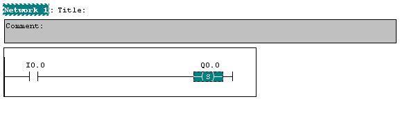
G) Set Coil :-
- The set coil is used to set the output to the one (1) sate when the set coil is energized.
- The energized output only get reset by the reset coil of the same address.
Note :- if the both inputs of the set and reset coils are on then the Output will not gets energize.
H) RS flip flop:-
- When I0.1 = 1 then the RS flip-flop sets to 1 and output Q0.0 sets to 1 state (ON).
- When I0.0 = 1 then the RS flip-flop sets to 0 and output Q0.0 sets to 0 state (OFF).
- When I0.0 and I0.1 both are ON (1) then the RS flip-flop follow set condition and output goes ON i.e. Q0.0 sets to 1 state (ON).

I) SR flip-flop :-
- When I0.0 = 1 then the SR flip-flop sets to 1 and output Q0.0 sets to 1 state(ON).
- When I0.1 = 1 then SR flip-flop sets to 0 and Output Q0.0 sets to 0 state (OFF).
- When I0.0 and I0.1 both are = 1 then SR flip-flop follow the reset condition and output goes OFF i.e. Q0.0 sets to 0 state (OFF).

J) Negative Edge detection:-
- Negative edge detection detects the change in signal from 1 to 0 (ON to OFF) and pass one short pulse when input changes from 1 to 0.
- In below fig. negative edge detection is used to set the output Q0.1 i.e when input changes from ON state to OFF state it sets output to 1(ON).

K) Positive Edge detection :-
- Positive edge detection detects change in signal from 0 to 1 (OFF to ON) and pass one short pulse when input changes from 0 to 1.
- It works exactly opposite to the Negative Edge detection.In Below fig. when input changes from OFF state to ON state it reset the output.

Comments
Post a Comment